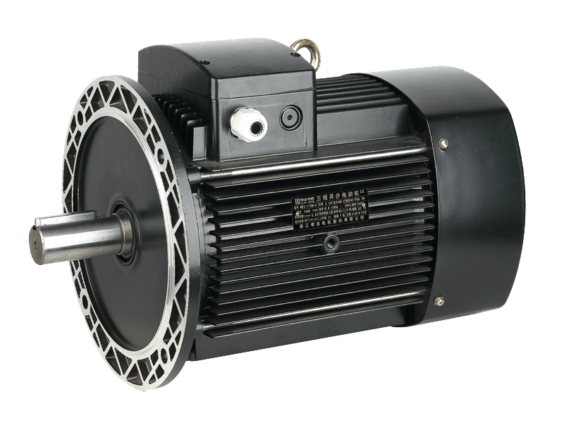
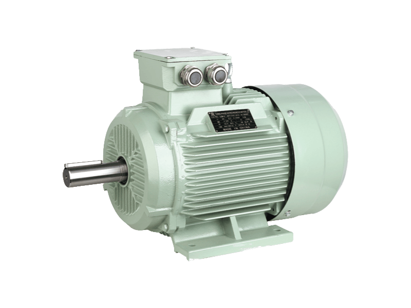
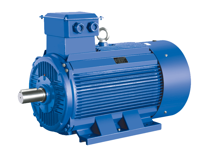
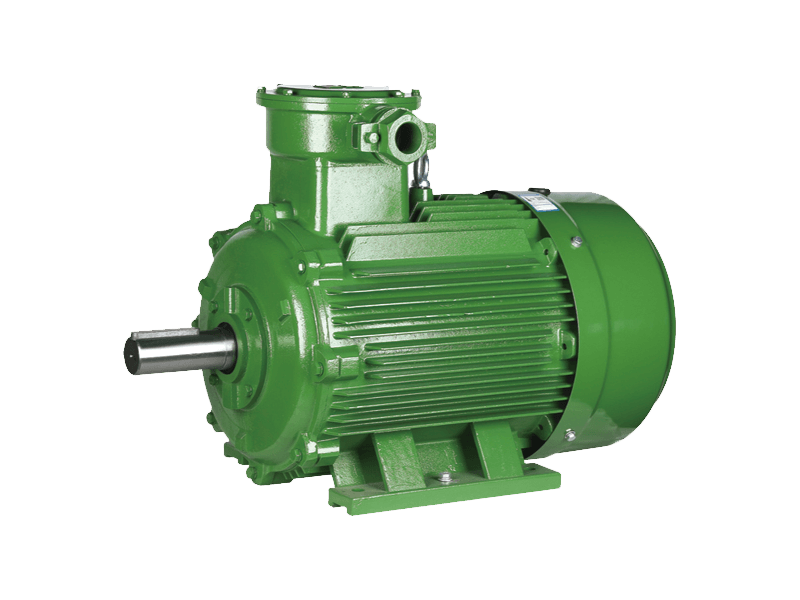
The common control methods of three-phase asynchronous motors include one-way start and stop control, forward and reverse start control, and Y-△ step-down starting control.
1. One-way start-stop control
Three-phase asynchronous motor one-way start-stop control circuit is often used for hydraulic steering gear, blower, electric grinding wheel, oil pump and other motor control equipment that requires one-way operation
When starting the motor, first close the power switch S. When the start button SB1 is pressed, the AC contactor coil KM is energized, the KM main contact is closed, and the motor is connected to the three-phase power supply to start. At the same time, the KM auxiliary contact connected in parallel with SB1 is also closed. When SB1 is released, the contactor coil remains energized, and the motor M continues to run. This auxiliary contact is called a self-locking contact. When the motor M needs to be stopped, press the stop button SB2, the contactor coil KM loses power, the KM main contact and the auxiliary contact are both disconnected, and the motor M stops.
2. Forward and reverse start control
The main circuit of the forward and reverse starting control circuit uses two AC contactors KM1 and KM2 to change the power phase sequence of the motor. When KM1 is energized, the motor rotates forward, and when KM2 is energized, the two phases of the power cord are connected to the motor. Stator winding, the motor reverses.
The auxiliary normally closed contacts KM1 and KM2 of the contactor ensure that the two contactor coils cannot be energized at the same time. This control method is called interlock or interlock. These two auxiliary normally open contacts are called interlock or interlock contact. point.
Measure the main circuit:
(1) Press the contactors KM1 and KM2 respectively, and connect the two test leads to the power supply terminal respectively, and the resistance between the motor windings should be measured. (2) Check the commutation of the power supply, connect the two test leads to the power access terminal and the electromechanical access terminal respectively, press KM1 to measure the resistance value R0, and press KM2 to measure the resistance between the two phase windings of the motor. .
Measuring control circuit: Connect the test leads of the multimeter to the control circuit access terminals to perform the following measurements. (1) Measure the start and stop control. Press the contacts of KM1 and KM2 respectively, and the resistance value of the KM1 and KM2 coils should be measured. While pressing the KM1 or KM2 contact frame, press SB3 again, the multimeter should display the circuit From on to off, it shows that the start and stop control circuit is good. (2) To measure the self-protection circuit, press the KM1 and KM2 coils to measure the resistance of the coils. If it is abnormal, check the wiring in the button box and the self-holding contact wiring of the contactor. (3) Measure the button interlock circuit, connect the two pens of the multimeter to the control circuit access terminals respectively, press the KM1 contact holder to measure the resistance of the KM1 coil, and then press SB2 to make the normally closed contact When disconnecting, the multimeter displays from on and off; when SB1 and SB2 are pressed at the same time, whether the contacts of KM1 or KM2 are closed or open, the multimeter displays open. (4) Check the overload protection link.
3. Y-△ reduced-voltage starting control Y-△ reduced-voltage starting circuit is often used for reduced-voltage starting control of motors that start at light load or no-load. Because of the button operation, the contactor is used to switch on the power supply to change the connection method of the motor winding, so it is convenient to use.
Press the start button SB1, the time relay KT and the contactor KM2 are energized and closed at the same time, the normally open main contact of KM2 is closed, the stator winding is connected into a star, its normally open auxiliary contact is closed, and the contactor KM1 is connected. The normally open main contact of KM1 is closed, the stator is connected to the power supply, and the motor starts under the star connection. A pair of normally open auxiliary contacts of KM1 are closed for self-locking. After a certain delay, the normally closed contact of KT is disconnected, KM2 is reset after power failure, and the contactor KM3 is energized and closed. The normally open main contact of KM3 connects the stator windings into a triangle shape, so that the motor can operate normally under the rated Y-△ step-down starting control voltage.
When inspecting the main circuit, disconnect the control circuit:
(1) Check the control function of KM1, connect the two test leads of the multimeter to the lower terminal of S and the U1 terminal on M respectively, and measure it as open circuit. Press the KM1 contact point to measure as a path, and then use the same method to measure V1 and W1. (2) Check the Y-shaped wiring start, press the multimeter pen to the two phases under S, press the contacts of KM1 and KM2 at the same time, measure the winding resistance between the two phases of the motor, and measure the other two phases in the same way. (3) Check the △-shaped running line, press the multimeter pen to the two phases under S, press the KM2 and KM3 contacts at the same time, and measure the resistance value of the motor two-phase winding in series and then in parallel with the third phase winding.
When checking the control circuit, first connect the main circuit, and connect the multimeter test lead to the two phases of the lower terminal S for measurement:
(1) When measuring the Y-shaped starting control, press the KM1 and KM2 contacts to measure the parallel resistance of the two coils. After loosening the two contactors touch KM1 and KM2 to reset, then press the KM1 contact to measure If the result is the same as pressing the two contactors, it means that the starting circuit is normal. (2) Check the Y-shaped control circuit, press the KM1 and KM2 contacts at the same time, and after measuring the resistance of the two coils in parallel, press KM3 to disconnect the normally closed contact, so that the multimeter displays the resistance value (for KM1 coil resistance value), then loosen the KM2 contact and press the KM1 and KM3 contacts at the same time to measure the parallel resistance of the two coils KM1 and KM3.
